Contactor Starter Wiring Diagram
Typical wiring diagrams for push button control stations 5 explanation of symbols momentary contact push button auxiliary contactsoperate when operating coil of contactor depressing button opens and parent switch. Crabtree garage consumer unit wiring diagram.

Contactor Starter Wiring Diagram ILMIOPICCOLOMONDOSUKY
Single phase motor connection with magnetic contactor wiring diagram.
Contactor starter wiring diagram. A wiring diagram is a simplified standard pictorial depiction of an electric circuit. Starter contactor (aka starter relay) is an “intermittent duty” relay meaning it is designed to be turned on only for short periods of time. 3 phase motor contactor wiring diagram a novice s guide to circuit diagrams.
Wiring diagram for motor starter 3 phase controller failure relay electrical pleasing thre electrical circuit diagram electrical wiring basic electrical wiring. They are used in applications which do not require undervoltage protection. Connect power and ground leads from a fused disconnect or circuit breaker directly to the magnetic starter.
The diagram symbols in table 1 are used by square d and where applicable conform to nema national electrical manufacturers a ssociation. Power power coil gets ground from mounting bracket. The design of this type of contactor is most advanced among all other types of contactors.
Contactor coil wiring diagram.wiring diagram book a1 15 b1 b2 16 18 b3 a2 b1 b3 15 supply voltage 16 18 l m h 2 levels b2 l1 f u 1 460 v f u 2 l2 l3 gnd h1 h3 h2 h4 f u 3 x1a f u 4 f u 5 x2a r power on optional x1 x2115 v 230 v h1 h3 h2 h4 optional connection electrostatically shielded transformer. A wiring diagram is a simplified traditional pictorial representation of an electrical circuit. Contactor breakers limit switch no static control standard elementary diagram symbols.
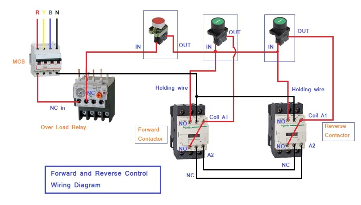
3 phase contactor with overload wiring diagram. We will use a contactor, an auxiliary contact block, an overload relay, a normally open start pushbutton, a normally closed stop pushbutton, and a power supply with a fuse. First of all wire the cb circuit breaker but do not switch on.
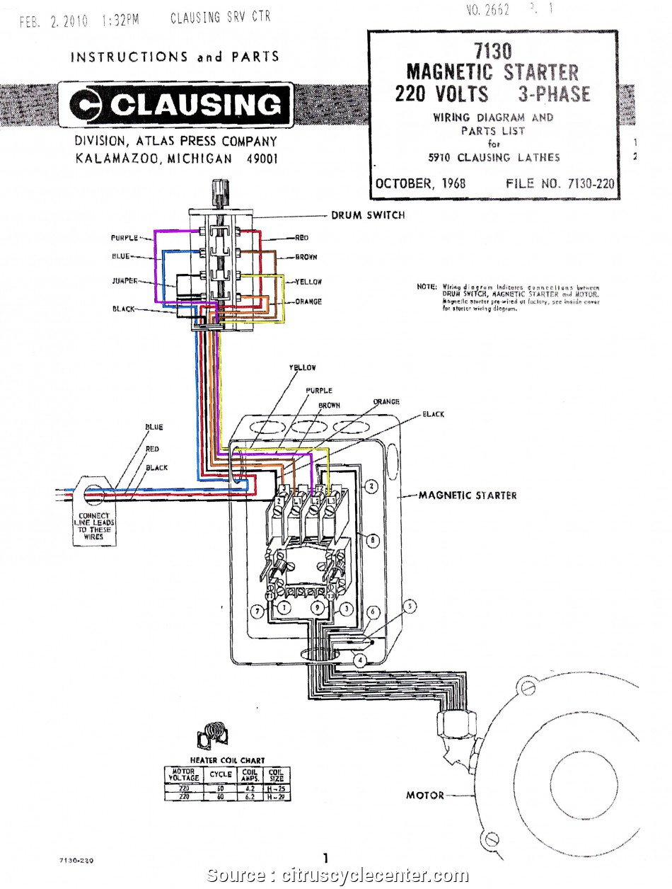
The power source is coming to light fitting. Collection of ac contactor wiring diagram. Use the wiring diagrams on the back of this sheet to install and connect power wires for the starter and motor.
When you press the start button and the stop button is not pressed the 24vdc relay energizes and it pulls in the r1 contactor that feeds three phase power to the motor. It didn t come with any documentation and the website does not. Otherwise the arrangement wont function as it.
Wiring diagrams sometimes called main or construc tion diagrams show the actual connection points for the wires to the components and terminals of the controller. Relay and contactor wiring diagram.single pole contactor relay wiring diagram 240v single pole means that it can only control a single circuit and single throw means that there are only two positions the switch can be in one on and one off state mechanical relays do not the esd5 series is an accurate solid state delayed interval timer it offers a 1a steady 10a inrush. Dol motor starter with 230v contactor.
In above contactor wiring diagram i shown 3 phase 440 volts 4 wire system. How to wire a contactor and motor protection switch. Typically a contactor is activated by a remote switch or other controlling electrical device.
How to wire a contactor and overload ? You must watch this video! Single phase motor contactor wiring electrical wiring electricity electrical engineering.
3 phase contactor with start stop wiring diagram i 2020 for 3 phase motor controlling diagram and procedure follow the below tips. 3 phase contactor with start stop wiring diagram i 2020. Contactor wiring diagram start stop;
T1 and t2 are the corresponding motor out connections and should be carried through to the motor. Pdf contactor wiring diagram with timer. 45 amp cooker socket control unit white crabtree 4520 1 clever 3 phase contactor wiring diagram start stop 3 phase contactor.
How to wire an air conditioner for control 5 wires the diagram below includes the typical control wiring for a conventional central air conditioning systemfurthermore it includes a thermostat a. Wiring a contactor is a safe method for controlling electrical power. Basics 9 416 kv pump schematic.
It includes guidelines and diagrams for different types of wiring techniques along with. Refer to the motor manufacturers data on the motor for wiring diagrams on standard frame ex e ex d etc. 3 phase start stop wiring diagram electrical circuit diagram circuit diagram electrical diagram.
Figure 1 is a typical wiring diagram for a three phase magnetic motor starter. The above diagram is a complete method of single phase motor wiring with circuit breaker and contactor. Contactor wiring diagram start stop, the above diagram is a complete method of single phase motor wiring with circuit breaker and contactor.
Iec contactor wiring diagram bureaucraticallyfo. Otherwise the arrangement wont function as it. Note that one one of the contactor acts as a switch for the start button.
With this sort of an illustrative manual, you are going to have the ability to troubleshoot, stop, and total your tasks without difficulty. A simple circuit diagram either of the two start buttons will close the contactor, either of the stop buttons will open the contactor. And if you learn something from the diagram then also share this post….
Magnetic contactor wiring diagram pdf.air conditioner contactor wiring diagram inspirationa wiring diagram. 3 pole contactor without base contact 4 pole contactor with 4 n.o. This contactor draws about 4a at 14v.
Wiring diagrams do not show the operating mechanism since it is not electrically controlled. Wiring diagram and schematics this place is a growing library of the schematics, wiring diagrams and technical photos. This will mean that you are going thru the contactor and overload three times which the overload will see as the same effect as a three phase mo.
“s”terminal positive power from control unit or starter button activates coil (closes contactor).

Single Phase Motor Contactor Wiring Diagram

Get Cutler Hammer Contactor Wiring Diagram Sample

Contactor Wiring Diagram Start Stop Pdf

Contactor Wiring Diagram 6 Electrical circuit

Electrical Contactor Wiring Diagram Download

WAZIPOINT

3 Phase Contactor Wiring Diagram Start Stop Cadician's Blog

Motor Starter Wiring Diagram Start Stop Free Wiring Diagram

36 Contactor Diagram Wiring Diagram Online Source

Contactor Coil Wiring Diagram Wiring Diagram Line

Irrigation Pump Start Relay Wiring Diagram Collection

Contactor Wiring Diagram For 3 Phase Motor with Overload

DOL Starter Wiring Diagram For 3 Phase Motor Controlling

3 Phase Contactor With Overload Wiring Diagram Pdf

Contactor Wiring Diagram Pdf 3 Phase Contactor Wiring

AC Blower Motor Wiring Diagram furthermore 3 Phase Star

Direct Online Starter Animation Diagrams
3 Phase Contactor Wiring Diagram Start Stop Cadician's Blog
No Nc Contactor Wiring Diagram For Your Needs